Sequence Component Filter Circuits And Its Phasor Diagram Ph
Sequence components – voltage disturbance Rl circuit phasor diagram Phasor diagram of capacitor
Active band-reject filter under Audio Filters Circuits -12198- : Next.gr
Solved for the following filter circuit with component Solved for the following filter circuit with component Sequential circuits for electromagnetic filter.
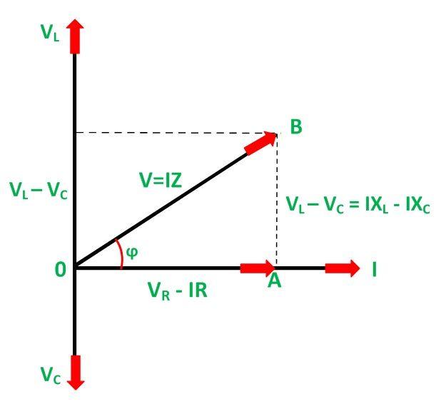
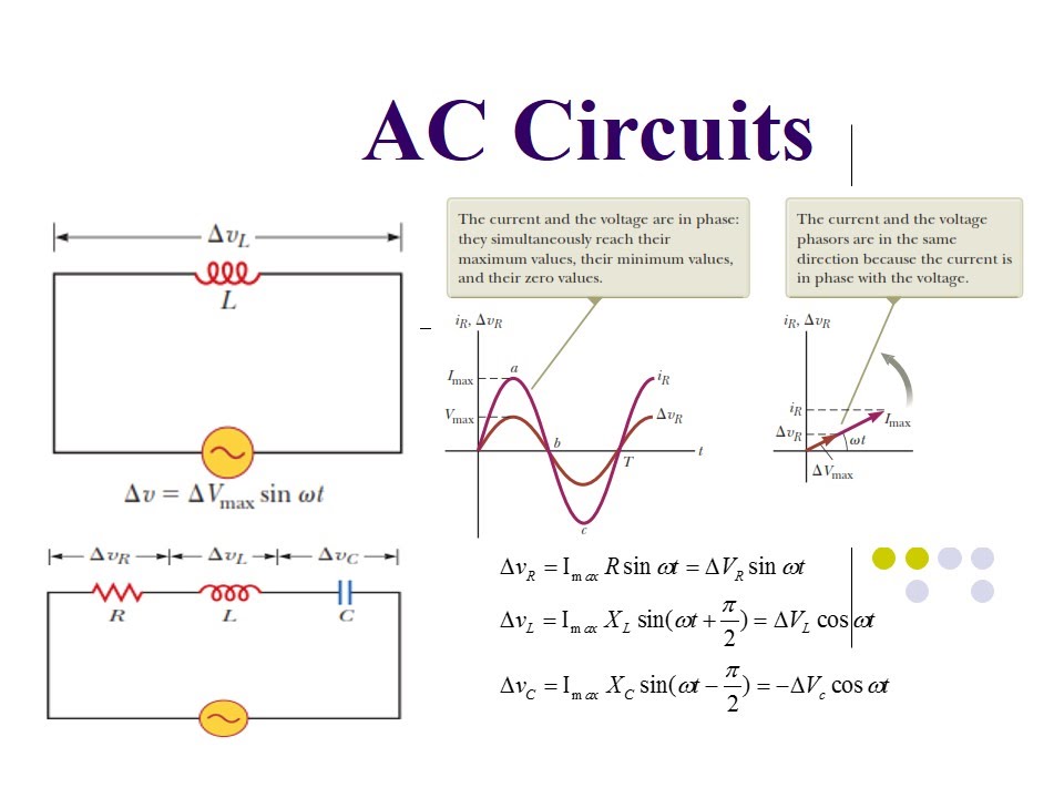
Rlc series circuit
Rl circuit phasor diagramPhasor diagram showing different positive-sequence currents i and Phasor rlc impedanceElectronic – understanding the circuit diagram on a filter – valuable.
Sequence components positive negative zero voltage system power disturbance calculateComponent sequence phasor symmetrical plotting filter diagram using thanks Microfilter circuit diagramGeneralize impedance to expand ohm’s law to capacitors and inductors.

Solved for the following filter circuit with component
Plotting symmetrical component phasor diagram using sequence componentPhasor positive fault sequence currents Phasor diagrams lcr circuitsFilter circuit diagram.
Phasor diagram showing different positive-sequence currents i andPlotting symmetrical component phasor diagram using sequence component Ecg circuit filter diagram back schematic circuits analog build step three need help electrocardiograph electrodes made electrode utah eng gifWhat is shunt capacitor filter? working, diagram & formula.
Filter component sequence plotting phasor symmetrical diagram using
Capacitors impedance lagging ohm inductors phasor inductor leads ohms generalize inductive dummiesSolved for the following filter circuit with component Active band-reject filter under audio filters circuits -12198- : next.grPhasor diagram rlc circuit series.
Flashing 3mm led'sNeed help in circuit diagram's filter [diagram] sequence diagram formatSolved for the following filter circuit with component.
Filter circuit diagram
Currents fault sequence flows diagram fx phasorInteractions creately diagrams component interact used Ac source in circuit diagramElectronic – how to go about determining the component values of the.
Filter basics part 2: designing basic filter circuitsSolved for the following filter circuit with component An image of a computer screen showing the flow diagram for a project inCircuit diagram of series filter.

What is filter circuit and its types
Sequence diagram tutorial – complete guide with examplesUml paradigm diagrams sysml interface component .
.


Solved For the following filter circuit with component | Chegg.com

Plotting symmetrical component phasor diagram using Sequence Component

an image of a computer screen showing the flow diagram for a project in

Plotting symmetrical component phasor diagram using Sequence Component

Electronic – How to go about determining the component values of the

filter circuit diagram - Wiring Diagram and Schematics

Active band-reject filter under Audio Filters Circuits -12198- : Next.gr